Useful information
On the following pages you will find a great deal of useful information on winding technology. Should you still have questions or suggestions, please contact us directly.
Tensile force control
A tensile force control system is necessary in many production areas in which wound materials, such as wires, fibre optic cables, chemical and textile fibres are manufactured, refined or processed. Depending on the manufacturing process, the physical properties of the product and the effective velocity required, different requirements are set for tensile force control.
The general trend towards the miniaturisation of products increases the need for processing more and more delicate wires and fibres. Here, tensile force control is an important prerequisite to be able to process delicate materials in general.
Tensile force control methods
Depending on the requirement, cost-effectiveness and technical options, there are different methods to control the tensile force in a production process. The tensile force of material sold by the metre or the wound material must be adjusted accurately for a processing procedure that rewinds, strands or coats wires, for example. The basic requirements for tensile force control are explained here using an application example in the form of a simple rewinder for wires.
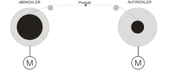
Fig.1 Schematic diagram of unwinders and winders |
An unwinder is shown on the left hand side of Fig. 1 and a winder on the right hand side.
The tensile force must be obtained so as to guarantee that the wire is fed in the best possible way. If the tensile force of the wire is too low, this will lead to poor winding layers or to the wire sliding off the guide roller and thus to the process stopping. If, on the other hand, the wire is stretched so much that it breaks, the tensile force is too high.
The two extremes show that the tensile force must not only be adjusted to the processing procedure but also to the physical properties of the product to be used in each case. The requirements for tensile force control are, however, considerably higher so that the wound material can be processed perfectly: The damping characteristic of a fibre optic cable changes if the tensile stress changes. The tensile stress must be kept constant during processing to ensure the consistent quality of the fibre optic cable. Fluctuations in tensile force lead to poor quality winding material and must therefore be prevented.
During the rewinding process different parameters change, such as that of the spool diameter and with this the revolution speed of the unwinder. Regardless of the changing sizes the tensile force control must be able to keep the tensile force constant. Another requirement is determined by the effective velocity of the wire. The faster the effective velocity, the more dynamically must the tensile force control also be able to work.
Current tensile force control methods are:
- Sagging control
- Torque control
- Braking procedure
- Drive control with force measuring heads
- Dancer position control
The function of the methods above, which are all used in industry, are explained in the menus on the left hand side. As there are many variation and combination options, only a rough summary can be given here.
Dancer control
The drive control with a dancer position is based on the sagging control with the important difference that the tensile force is not controlled by the inherent mass of the product but by an external force that acts on the product.
|
Fig. 1 Schematic circuit diagram of the dancer control |
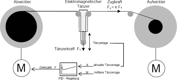
The dancer position control is a tried and tested method for the active tensile force control of wound material. Active tensile force control uses drive motors for the general transport of the wound material, for example, in the form of a spool drive instead of braking systems. The schematic circuit diagram shows the rewinding procedure of wound material from the unwinder to the winder with dancer position control. In the schematic circuit diagram it is assumed that the winder winds the product at a specified speed. The unwinder must follow the winder so that a required tensile stress is set. This is achieved by the wound material experiencing a force via a moveable return pulley that corresponds in a fixed ratio to the tensile stress. In the schematic circuit diagram illustrated a positive acceleration of the winder would lead to an upward movement of the moveable return pulley. With negative acceleration the return pulley would move down accordingly. The upward and downward movement is also called dancing which is where the synonym dancer comes from. According to the pulley block principle, the tensile force is proportional to the dancer force. The dancer position is, in turn, used to control the rpm of the drive motor, preferably with a PID controller. If the dancer moves upwards, the control deviation causes the positive acceleration of the unwinder and vice versa. The dancer force must always be kept constant regardless of the position of the dancer so that the tensile force does not change in the event of a control deviation.
With traditional dancer systems that consist of weights, pneumatic cylinders and (or) springs, only relatively rough tensile force controls with corresponding tensile force fluctuations can be implemented. This is due to the physical property of the dancer force. With dancers with weights the force changes according to F = ma already due to the dancer movement. The inertia inevitably causes a change in the tensile force. Springs always have another force in proportion to the spring length and contradict the necessity for a constant dancer force which is difficult to control even with special pneumatic cylinders.
Traditional methods come up against their technical limits, especially for tensile force control of delicate products. For this reason, Supertek GmbH developed an electromagnetic dancer that is based on an electromagnetic force procedure patented by Supertek and can create a highly dynamic, constant dancer force that does not depend on the position of the dancer. Force stresses in the range of 0.0 cN to 500 cN with a resolution of 0.1 cN can be controlled with the EDL 50 electromagnetic dancer. Where other systems fail, by using the electromagnetic dancer, even the most delicate wound materials can now be processed quickly, accurately and easily.
As a result new, more efficient, more cost-effective production options are opening up.
Supertek GmbH supplies the electromagnetic dancer including the electronic control unit as a component for upgrading existing systems or to manufacture new machines.
Supertek will be pleased to advise you. Just call us.
Sagging control
As the term suggests, sagging control is originally a control unit with an open control circuit. This type of tensile force control is used in production processes where it is sufficient to control the tensile force by the product's own weight by the product simply dipping between two revolving rollers. This type of tensile force control is used mainly with sheet materials, such as metal sheets, fabrics or paper but also, for example, for simple rewinders for cables. Sagging control is one of the simplest forms of tensile force control and has the known disadvantages of a control unit compared with a regulating system. Today, however, the term sagging control means rather a generic term and can, therefore, also stand for a sagging regulating system. In most cases optical distance sensors are used for sagging regulation systems. These measure the sagging position and thus have a retrospective effect on a drive system.
If the inherent dimensions or the sagging length is too low for a tensile force, help can be provided, for example, with an external force. If this procedure is used for a sagging regulation system, it is called dancer position control.
The sagging method described can, for example, be ruled out for thin wires as their own dimensions are not sufficient for a practical function. The principle that uses the inherent dimensions of the wire is, however, used for thin wires with what is called the whisker disc and should therefore not go unmentioned. The whisker disc uses the centrifugal force that is exerted by the rotating spool in order to unwind the wire. The centrifugal force that corresponds to the tensile force depends on the speed and the diameter of the rotating spool and the dimensions of the wire. This results in problems of approaching or braking and guiding the wire. The tensile force cannot be set regardless of the speed. Vibrations on the wire have a negative effect on the processing.
Supertek will be pleased to advise you. Just call us.
Torque control
The torque of the unwinder or winder drive is controlled by the torque control. The tensile force control via the torque control seems to be a suitable method with today's drive technology but entails certain restrictions. As the circumference of the spool changes during winding and unwinding, this causes a change to the wire's tensile force at a constant torque. The torque control can be used for minor changes in circumference or with permissibly wide tensile force tolerances, specially in the event of high tensile strengths. In addition the torque can be adjusted to the circumference of the spool. A measuring and adjustment device that permanently determines the circumference is needed for this. The torque must therefore be adjusted to the circumference and be continuously calculated. The tensile force control using the torque control is made more difficult by acceleration processes. Torque controls are therefore rather unsuitable for very accurate or very small tensile stress requirements.
The greatest disadvantage with torque control, unlike the dancer position control, is that a control deviation of the drive motor has a direct effect on the tensile stress. There is also no buffer for external interference with the torque control.
Supertek will be pleased to advise you. Just call us.
Braking procedure
The braking procedure is mentioned separately here as a simple form of torque control as the braking procedure is only limited by the torque and is not actively controlled by a drive motor.
During the braking procedure the tensile force is set in its simplest form by the brake only being triggered when a predefined tensile force is reached. Here the product can be braked by brake rollers or directly on the shaft of the unwinding spool. Depending on the requirement, the braking effect is only guaranteed using a mechanical, hydraulic or pneumatic or with an electromechanical braking device. The mechanical braking procedure is performed, for example, with weights or springs that create the braking force with their own force. The braking force and, together with it, the tensile force can be changed manually with springs or by varying the length of the spring. Even torque limiters that create a force with permanent magnets are used in the braking procedure. Electromechanical brakes work, for example, with magnetic powder brakes, electromagnets or motor-driven drives. The advantage over mechanical systems is primarily that electronic control units can be used that make a lower correcting variable deviation of the tensile force possible.
With brakes that do not brake the spool but the wound material directly via pressure rollers on what is called a capstan, the product is often unwound head first where twisting is unavoidable so that flat leads or films cannot be processed with this procedure.
A combination of the sagging control and the subsequent capstan to use the braking method is possible in order to avoid twisting. Basically, however, braking systems can only control tensile stress sufficiently precisely to a very limited extent.
Supertek will be pleased to advise you. Just call us.
Force measuring systems
The tensile force can be determined using force measuring heads and controlled using a drive controller. The measurement is performed directly on the product, for example, using rollers that are connected to a force measuring device. Different procedures are used to measure force depending on the accuracy requirement and the size of the tensile force. These include pressure sensors and expansion measurement strips and piezo electric and electromagnetic procedures that are described as force and pressure sensors or sensors or as weighing cells. Basically, a very accurate measurement of the tensile force can be achieved with a force measuring head. A precise actual value is still no indication of a good adjustment. The requirement for the drive control is very high because a control deviation of the drive leads directly to an expansion or relaxing of the product.
Supertek will be pleased to advise you. Just call us.
